

|
|
|
|
 |
|
 |
BMW Garage | BMW Meets | Register | Today's Posts | Search |
 |

|
BMW 3-Series (E90 E92) Forum
>
Help wiring digital VEI Boost Gauge
|
 |
| 01-23-2009, 04:08 PM | #1 |
|
Colonel
 
208
Rep 2,558
Posts |
Help wiring digital VEI Boost Gauge
Hey guys... I'm going to install the old-school rixeffects VEI boost gauge with pod tomorrow... I'm a bit confused with the wiring, as I don't have much electrical-wiring experience...
I want to do the dimmer switch, so I need to connect the capacitor and resistors to the circuit as well... here's the diagram in the directions: 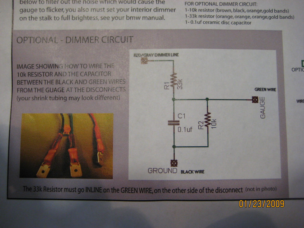 And here are the connectors I have: 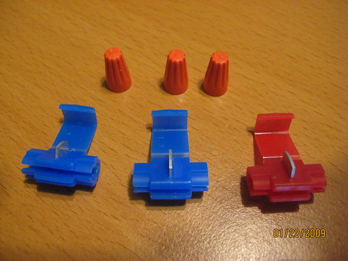 So first thing first... I assume the blue and red connectors are to be used to connect the extension wires to the cigarette lighter wires. Am I supposed to use the cone-shaped connectors to connect the gauge wires to the extension wire, then? I don't even really know how these work... just get one wire from the gauge and one wire from the extension wire, put them in there, and twist? Also, in the circuitry diagram, it appears that R1 connects the "green wire" in serial with the "red/gray dimmer line". How do I make the connections to the resistor? I hope my questions were clear... any help will be great... thanks guys!!
__________________
'07 Space Gray 335i coupe - R.I.P.
 COBB ProTuned | AMS | CP-e | BMS | Quaife |
| 01-23-2009, 11:31 PM | #2 | |
|
274
Rep 6,510
Posts |
Quote:
The 33k resistor goes on the green wire, before it connects to the extension wire. You will have to twist or solder it in-line. It will look like this: Gauge Green wire ====----(resistor)----=====extension wire. And then the other 2 components (resistor and cap), both go between black and green, at the wire nuts. Sorry, its kinda pain in the butt, but without it, it will flicker because the dimmer line is PWM.... on the vent gauge, I integrated these components onto the gauge circuit board, so there is no need for them anymore. -Rick |
|
|
Appreciate
0
|
| 01-23-2009, 11:34 PM | #3 | |
|
Colonel
208
Rep 2,558
Posts |
Quote:
One more thing... when I put the wires into the blue/red wire nuts, do I need to strip the insulation off the wire, or are these made to cut through the insulation? I figured I should strip the wires first, especially if I am going to add the resistor/capacitor between two of the lines... yes?
__________________
'07 Space Gray 335i coupe - R.I.P.
COBB ProTuned | AMS | CP-e | BMS | Quaife |
|
|
Appreciate
0
|
| 01-23-2009, 11:39 PM | #4 | |
|
274
Rep 6,510
Posts |
Quote:
|
|
|
Appreciate
0
|
 |
| Bookmarks |
|
|


